Manual routing and traditional sawing were engineered for a different era — one where tolerances of ±1/16″ were acceptable and complex geometries simply weren’t on the order sheet. Today, that gap between what conventional fabrication delivers and what modern industrial projects demand has become a critical liability.
The manufacturing landscape has shifted decisively toward 2.5D and 3D geometries — contoured housings, compound-angle brackets, intricate panel cutouts, and multi-axis profiles that no hand-guided tool can reproduce consistently at scale. A fabricator running a manual router across a sheet of aluminum or high-density polyethylene introduces human variability at every pass. Repeatability collapses. Scrap rates climb. Project timelines stretch.
Precision fabrication is no longer a competitive advantage — it’s the baseline expectation. The global CNC router market is projected to grow at a CAGR of 4.9% through 2027, a figure driven directly by industrial demand for automated, high-accuracy cutting across metals, plastics, and composites.
This is precisely where a professional CNC routing service changes the equation. Far beyond its origins in woodworking and signage, CNC routing has evolved into a genuine precision solution for aerospace panels, industrial enclosures, and structural plastic components — materials and applications where tight-tolerance part production is non-negotiable.
Understanding why this technology closes the precision gap starts with the mechanics powering it.
What is CNC Routing? The Mechanics of 3-Axis Mastery
Where traditional fabrication methods rely on operator skill and fixed toolpaths, CNC router services operate on a fundamentally different principle — programmed precision replicated across every single cut. Understanding the mechanics behind that precision starts with three axes of movement.
Process Flow: From File to Finished Part
- Design (CAD) — Engineers produce a detailed digital blueprint specifying geometry, tolerances, and material constraints.
- Toolpath Generation (CAM) — CAM software translates that design into machine instructions, assigning cutting speeds, depths, and bit selections.
- Axis Initialization — The machine homes to a reference point, establishing the X (horizontal), Y (longitudinal), and Z (vertical depth) coordinates.
- Material Fixturing — The workpiece is secured to the bed using vacuum tables, clamps, or jigs to eliminate movement during the cut.
- Execution — The spindle engages, and the router follows the programmed toolpath with sub-millimeter accuracy.
- Quality Verification — Finished parts are checked against the original CAD file, often using digital calipers or CMM scanning.
> AXIS SPEC: CNC routers utilize a 3-axis (X, Y, and Z) movement system, enabling the precise cutting of complex 2.5D and 3D shapes that are physically impossible for manual tooling to replicate consistently. (Thomasnet)
The Z-axis is where the real complexity lives. By controlling exactly how deep the spindle plunges — and varying that depth dynamically mid-cut — the machine can produce tapered profiles, contoured surfaces, and pocket geometries in a single pass. This eliminates the multi-step operations that compound error in manual workflows.
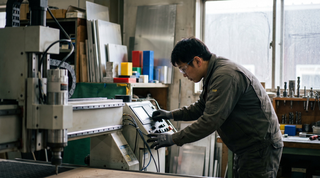
> RPM CALLOUT: High-speed spindles reach 18,000 to 24,000 RPM, producing the clean, chip-free edges that heat-sensitive materials like acrylic demand and that downstream finishing steps depend on.
CAD/CAM integration is the connective tissue of the entire process. A dimensional change made in the digital file propagates instantly into the toolpath — no re-jigging, no manual recalibration. Understanding how tight tolerance standards apply at this stage helps clarify why CNC routing consistently outperforms hand-guided alternatives.
Precision isn’t a byproduct of CNC routing — it’s the architecture the entire process is built around. That foundation becomes especially critical when the material in question demands both structural integrity and surface quality — which is exactly where the next discussion begins.
Industrial Capabilities: Precision Cutting for Aluminum and Beyond
With the mechanical fundamentals of 3-axis CNC motion established, the real-world value of precision CNC routing becomes clear when applied to industrial materials — particularly non-ferrous metals and large-format structural components where traditional sawing simply can’t keep pace.
Aluminum Extrusions: Where Routing Wins
Aluminum is the defining test case for CNC routing superiority. Traditional sawing introduces heat buildup, burring, and micro-fractures along cut edges — problems that compound across production runs. CNC routing eliminates these variables through controlled spindle speed, optimized feed rates, and precise depth-per-pass management. As noted by xsftruss.com, achieving high-tolerance finishes on extruded aluminum sections is a primary advantage of routing over conventional sawing — a distinction that matters critically for truss systems, architectural millwork, and structural channel work.
The difference isn’t subtle. Clean, burr-free edges on extruded sections mean less secondary finishing, faster assembly, and components that meet specification without rework.
Material Versatility in Industrial Environments
Beyond aluminum, CNC routing handles a broad range of non-ferrous metals and engineered substrates with consistent precision. The table below outlines where routing creates the most measurable advantage:
| Material Type | Routing Benefit | Tolerance Level |
|---|---|---|
| Aluminum extrusions | Burr-free edges, no thermal distortion | ±0.005″ |
| Copper/brass sheet | Clean profiles, minimal material stress | ±0.008″ |
| Polycarbonate/acrylic | Chip-free cuts, optical-grade edges | ±0.004″ |
| Composite panels | Consistent depth, no delamination | ±0.006″ |
| HDU/signage foam | Intricate detail without tool drag | ±0.010″ |
For manufacturers scaling toward hybrid production strategies, routing pairs naturally with other precision processes — worth considering alongside additive manufacturing methods when complex geometries demand more than a single process can deliver.
Repeatability Across High-Volume Runs
Repeatability is where CNC routing separates itself from every manual alternative. Across 1,000-unit production runs, a properly calibrated router holds the same toolpath coordinates on part 1,000 as it did on part one — no operator fatigue, no drift. That consistency underpins quality certifications, traceability requirements, and the kind of dimensional reliability that industrial clients depend on at scale.
That precision doesn’t stop at the cutting path itself. The next consideration — how material is held, positioned, and optimized across a full sheet — is where vacuum nesting technology transforms efficiency even further.
Efficiency by Design: Vacuum Nesting and Material Optimization
Precision cutting capability only tells half the story. The other half — the one that directly affects your bottom line — is how intelligently a CNC routing operation manages the material being cut. This is where vacuum table nesting technology transforms a capable machine into a genuinely cost-efficient production system.
A vacuum table holds workpieces firmly against the bed using negative pressure, eliminating mechanical clamps that would otherwise interrupt the usable surface area. Nesting software then analyzes every part geometry in a production run and algorithmically arranges them across the sheet to minimize dead space between cuts. The result is measurably less scrap — particularly critical when working with expensive substrates like polycarbonate sheet, aerospace-grade aluminum, or thick HDPE stock.
“The integration of vacuum table nesting technology in CNC routing significantly reduces material waste by optimizing the placement of parts on a single sheet.” — Woodworking Network
For B2B clients evaluating CNC routing services near me, that reduction in waste isn’t just a sustainability metric — it’s a direct cost recovery. When substrate costs represent a significant portion of project spend, yield optimization can meaningfully shift project economics.
Business ROI benefits of vacuum nesting include:
- Lower material spend — More parts per sheet means fewer sheets purchased per production run
- Reduced scrap disposal costs — Less off-cut waste lowers handling and disposal overhead
- Environmental compliance support — Demonstrable waste reduction helps satisfy corporate sustainability reporting requirements
- Faster quoting confidence — Nesting software produces predictable material usage estimates, tightening budget accuracy
- Scalability across run sizes — Nesting efficiency applies equally to prototype quantities and high-volume orders, making it relevant at every stage of the transition from prototype to production
Understanding where efficiency gains live in a CNC process naturally raises the next question: which industries and applications are best positioned to capture them?
Strategic Use Cases: From Prototyping to Full-Scale Production
Precision cutting and material optimization, as covered in the previous sections, only create value when applied to real production challenges. What distinguishes modern CNC routing is the sheer breadth of industries it serves — from delicate prototype runs to high-volume architectural installations.
Aerospace and Automotive: Tight Tolerances, Demanding Materials
Problem: Aerospace and automotive suppliers need lightweight plastic and aluminum components that meet exact dimensional specs without the lead times associated with traditional machining.
Solution: CNC routing delivers repeatable cuts on materials like UHMW polyethylene, polycarbonate, and aluminum sheet with tolerances held to ±0.005″. In practice, this means interior trim panels, cable routing brackets, and structural spacers can move from CAD file to finished part rapidly — without requiring dedicated hard tooling.
Architectural Millwork: Large-Scale 3D Decorative Panels
Problem: Designers specify intricate 3D relief panels and decorative millwork that are impractical to produce by hand at scale.
Solution: CNC routing — including custom wood CNC routing for MDF, hardwood, and composite panels — allows architects to execute complex carved surfaces and repeating geometric patterns across full 4×8 or 5×10 sheet formats. Precision CNC routing transforms a designer’s digital vision into physical millwork with zero hand-finishing compromise.
The Prototyping Phase: Rapid Iteration Without Tooling Costs
Problem: Design teams need to test fit, form, and function quickly without committing to expensive injection molds.
Solution: The UWM Prototyping Center model — utilizing CNC routing for rapid fabrication and iterative design testing — is now standard practice. Teams can turn around machined prototypes in days, evaluate real-world performance, and refine geometry before scaling. This approach pairs naturally with agile mold development strategies downstream.
Signage and Display: Acrylic Fabrication at Speed
Problem: Display fabricators cutting acrylic at high speeds risk heat buildup, melting, and edge distortion.
Solution: High-RPM spindles paired with optimized feed rates and single-flute O-spiral bits evacuate chips efficiently, keeping cut edges clean and optically clear — no secondary polishing required.
Understanding how these outcomes are achieved in practice comes down to tool path strategy — which is exactly where the next section picks up.
Visual Guide: Mastering the CNC Routing Workflow
Seeing the spindle in motion transforms abstract tool path logic into something immediately intuitive. The video below captures exactly that — watch how the router navigates complex geometry, maintaining consistent depth and clearance across varying material densities.
What to watch for: Pay close attention to how spindle speed adjusts relative to feed rate — particularly during precision cutting for aluminum, where chip load management directly determines surface finish quality and tool longevity.
In practice, tool path visualization is where operators catch costly errors before the first pass ever begins. Clearance planning — accounting for fixture height, clamp positions, and material warping — separates a clean run from a scrapped sheet. Proper clearance strategy is the difference between a repeatable process and an expensive one. Understanding these variables prepares you to evaluate what a capable manufacturing partner brings to every project, which is exactly what the next section addresses.
Partnering for Precision: Why Oxrapid is the Choice for Industrial Routing
The technical challenges explored throughout this article — tight tolerances, complex 3D geometry, large-format materials, and seamless CAD-to-part transitions — demand a manufacturing partner equipped to handle all of them without compromise.
Tight tolerance repeatability isn’t a selling point at Oxrapid; it’s a baseline expectation. Every routing operation is held to exacting dimensional standards, ensuring that part 500 matches part 1 with the same precision that modern industrial applications require.
Complex geometries and oversized workpieces are where many operations fall short. Oxrapid’s capabilities span both, making it a reliable choice whether the job involves intricate 3D contours or full-sheet material processing. The workflow from uploaded CAD file to finished component is deliberately friction-free — no ambiguity, no costly interpretation errors.
Precision CNC routing at scale means nothing without process consistency — and process consistency starts with the right partner.
Explore our Advanced CNC Routing Services and get a quote tailored to your exact specifications.
Key Takeaways
- Lower material spend — More parts per sheet means fewer sheets purchased per production run
- Reduced scrap disposal costs — Less off-cut waste lowers handling and disposal overhead
- Environmental compliance support — Demonstrable waste reduction helps satisfy corporate sustainability reporting requirements
- Faster quoting confidence — Nesting software produces predictable material usage estimates, tightening budget accuracy
- Design (CAD) — Engineers produce a detailed digital blueprint specifying geometry, tolerances, and material constraints.