Ultrasonic thickness measurement can help inspect a machined wall when only one surface is accessible. The useful result is not simply the number on the gauge: it is a thickness reading tied to a known location, a suitable probe, material calibration and a credible return echo. A stable display alone does not prove that the instrument measured the intended wall.
For CNC machining projects with FUMING, define the wall-thickness requirement while reviewing the drawing. Decide whether ultrasound is the primary acceptance method, a screening method or a supplement to direct dimensional inspection. Those roles require different evidence and should not be left for the receiving inspector to infer.
Start with a location map, not a minimum reading
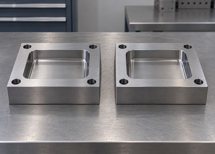
A pocket floor, cylindrical wall and transition into a corner are different measurement locations. Identify each required region on the drawing, including the surface from which the probe will approach. A single value labeled “wall thickness” is difficult to interpret when several walls have different nominal dimensions or tolerances.
Specify whether acceptance concerns selected points, a defined scan path or another approved coverage plan. Point readings cannot establish the minimum thickness everywhere between those points. If the design requires a minimum across a whole area, the inspection plan must explain how the coverage supports that decision.
Record the drawing revision, part identifier and manufacturing stage. A measurement taken before a final machining pass is not the delivered wall dimension. Keep the location references consistent between the machining plan, inspection report and any follow-up investigation so that measurements taken on different days can be compared.
Understand what the instrument converts into thickness
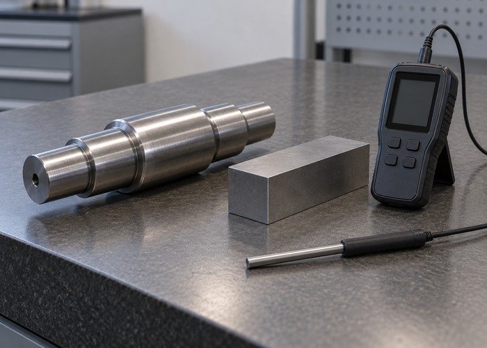
Evident’s introduction to ultrasonic thickness gauging explains that the instrument derives thickness from the travel time of a sound pulse and the material’s sound velocity. The usual pulse-echo arrangement allows access from one side, but depends on receiving and identifying the appropriate reflection from the opposite boundary.
The practical consequence is that the material setting belongs in the report. A stored setting named after a broad metal family is not sufficient evidence that it is appropriate for the actual material and condition. The responsible inspection team should establish calibration using the applicable procedure and suitable reference material.
Keep temperature in the record when it matters to the application. A part still warm from machining may not represent the condition used for calibration or dimensional acceptance. Agree conditioning requirements rather than assigning one universal waiting period to every material, wall size and shop environment.
Confirm the probe can measure the actual geometry
The measurement range belongs to an instrument and transducer combination, not to ultrasound in general. Review the proposed setup against the thinnest and thickest expected walls, material behavior and available contact area. A specification for a large flat plate does not automatically cover a small curved pocket wall.
Evident’s transducer selection guidance discusses thickness, material and curvature as selection factors. Use that principle to request an application check where access is restricted. Do not turn a general equipment capability range into an unsupported tolerance promise for the finished part.
On curved surfaces, consider whether the probe can sit consistently in the intended orientation. Near an edge or tight corner, the available contact patch may differ from the reference setup. Mark excluded or unreliable regions explicitly. Moving the probe to an easier nearby location changes the coverage and needs to be recorded.
Check calibration and echo interpretation separately
A current instrument certificate and a valid application setup answer different questions. The certificate does not establish that the selected material velocity, zero setting and echo interpretation are correct for this component. Retain the reference identity, relevant known dimensions, setup details and required checks during use.
Evident’s thickness gauging tutorial addresses calibration, geometry and operator-related factors. A qualified reviewer should assess uncertain echoes using the capabilities of the selected equipment. Do not select whichever displayed value happens to agree with the expected drawing dimension.
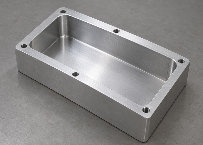
Use a known accessible feature or representative specimen for correlation when the approved plan calls for it. A direct measurement can help investigate a discrepancy, but only when both methods address the same location and condition. Comparing the thick rim of a cup with an ultrasonic reading farther down its wall does not isolate instrument error.
Keep surface condition and couplant under control
Document the tested surface as bare, coated or otherwise prepared. A coating may affect the measurement depending on the method and setup. If the equipment has a coating-handling mode, confirm its suitability for the actual application instead of assuming that every mode removes every coating contribution.
Identify the couplant and any relevant compatibility requirements. The inspection plan should address removal of residues when cleanliness or subsequent finishing matters. Do not introduce an unapproved fluid onto a functional or cosmetic surface simply because it produces an easier reading.
Roughness, contamination and inconsistent contact can complicate repeatability. Avoid altering the part without authorization to make inspection easier. If a local surface cannot support a reliable result, retain the limitation and obtain a suitable alternative measurement plan rather than treating a missing reading as a passing value.
Use a report that preserves the decision
| Record | Useful detail | Question it answers |
|---|---|---|
| Part identity | Lot, drawing revision and condition | Which delivered component was measured? |
| Coverage | Point map or approved scan extent | Where does the result apply? |
| Equipment | Gauge, transducer and setup identity | Can the measurement be reproduced? |
| Calibration | Reference and relevant settings | How was time converted to thickness? |
| Result | Units, individual readings and limitations | What was actually observed? |
| Acceptance | Limits, decision rule and disposition | Why was the part released or held? |
A summary minimum is useful only when its origin is retained. Keep the underlying readings and identify any rejected measurements with reasons. Do not average away a local thin region if the requirement applies to individual locations. Equally, do not classify a questionable echo as a physical defect without investigation.
For results near a limit, apply the agreed measurement uncertainty and acceptance approach. Display resolution is not the same as demonstrated measurement capability. The report should make the release decision understandable without requiring a later reconstruction of the inspector’s assumptions.
Resolve disagreement through a controlled comparison
If two parties report different wall thicknesses, first compare location maps, units, part temperature, surface condition and probe setup. Confirm the same material revision and manufacturing stage. Many apparent disputes involve different measurement questions rather than a disagreement about one physical dimension.
Retain the original results while a correlation check is performed. Agree who reviews the evidence, which method controls acceptance and how any additional sampling will be selected. Include the outcome in the quality assurance record so the next production lot uses the resolved approach.
Buyer questions
Does one passing point prove the entire wall meets the minimum?
No. It supports the identified location and method. Coverage must be appropriate to the actual drawing requirement, especially around transitions and localized machining features.
Can ultrasound replace every direct dimensional check?
No. Method suitability depends on geometry, material and access. Keep other required checks in the first-article inspection plan.
What should accompany an inquiry?
Send the drawing, minimum-wall requirements, proposed locations and acceptance method. Contact FUMING to review inspection access and reporting needs before the machining route is finalized.