A mold cooling connector handover should identify both mating halves, the fluid and operating conditions, the hose assembly and the circuit destination. Matching thread size or similar appearance does not establish interchangeability. The receiving team needs a controlled connection list that explains what fits, what is approved for the service and where each supply and return belongs.
This guide focuses on connection compatibility and changeover records. It complements cooling-flow and leak-test evidence but does not replace them. For a mold-making project with FUMING, include the intended machine interface and temperature-control equipment in the handover requirements before the tool is shipped.
Treat the connector as more than a thread
A connection can include a mold-side port, an adapter, a quick-coupling half, its mate, a hose termination and seals. Write down those interfaces separately. A nominal thread designation describes only one portion of the assembly. It does not establish the coupling profile, locking mechanism, valve arrangement or seal compatibility.
Record the manufacturer’s series and complete part numbers for both mating halves. Include any option codes that determine seals or configuration. If an interchange is claimed, ask for the applicable manufacturer confirmation and the conditions of that claim. Do not infer compatibility by observing that two halves appear to latch together.
DME’s mold cooling component overview distinguishes connector families, socket arrangements and seal-dependent service conditions. Use the documentation for the selected product to define the approved envelope; an example for one family is not a rating for a different assembly.
Define the actual fluid and operating envelope
Identify the temperature-control medium and its relevant composition, not simply the word “coolant.” Include additives or concentration where they affect selection. Provide the required operating temperature and pressure conditions to the component manufacturer or responsible engineer, including the relevant transient conditions. A cold shop-floor fit check cannot establish suitability for hot service.
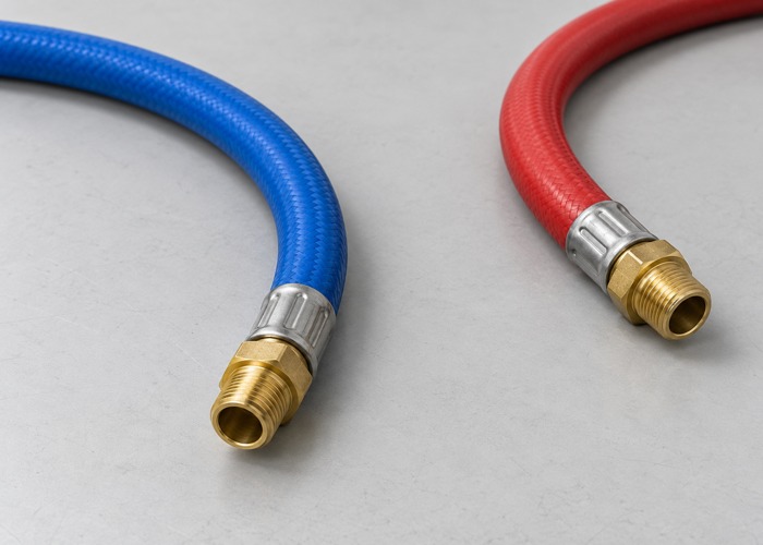
Review the complete hose and connector assembly. The rating of one component does not automatically apply to the hose, adapter, seal and mating half used with it. Preserve the source of each approved limit and any applicable conditions. Avoid presenting the highest number found in a catalog as the limit of the assembled system.
State whether connection or disconnection under pressure is permitted by the selected product and procedure. Do not assume that all quick couplings support that operation. Changeover instructions should reference the approved equipment isolation and handling procedure rather than encouraging operators to improvise when a connection resists release.
Use circuit identity that survives a machine transfer
Assign stable identifiers to each circuit and its supply and return. Place the identifiers in the circuit drawing, connection list and physical marking scheme. Color can help recognition, but the written identifier should remain sufficient when a hose is replaced or a label becomes difficult to read. Do not rely on the memory of the person who performed the first trial.
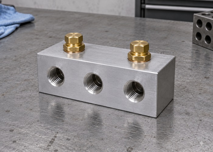
A receiving machine may use a different manifold arrangement from the original trial press. Provide an explicit mapping between mold circuits and the receiving interface. If adapters are required, identify their approved part numbers and locations. A bag of apparently suitable fittings does not provide a controlled transfer plan.
CUMSA’s mold accessories range lists cooling connectors, identification plates and hose retainers as distinct items. A useful handover likewise separates physical connection, identification and hose support. Specify the actual marking scheme and reviewed interface rather than assuming that an unlabelled fitting prevents cross-connection.
Make the connection list usable at the mold
| Field | Example of required information | Purpose |
|---|---|---|
| Circuit identifier | Unique designation linked to the drawing | Preserves identity through transfer and maintenance |
| Connection location | Mold side and physical port position | Prevents ambiguity between nearby ports |
| Mating pair | Series and complete part numbers for both halves | Defines the actual compatible interface |
| Fluid and conditions | Approved medium and operating envelope reference | Supports material and seal selection |
| Hose assembly | Assembly identification and approved routing | Connects component selection to the installed system |
| Verification | Drawing revision and completed checks | Shows what was verified before handover |
Use photographs to show orientation and access, while keeping part numbers in readable text. A photograph of a shiny coupling is rarely enough to identify a seal option or internal valve configuration. Maintain the list as a controlled document with the tool, rather than as an informal message that may not reach the next maintenance team.
Include any blanked, unused or reserved connections. State their purpose and the approved closure arrangement. Otherwise an unused port can be mistaken for a missing circuit or an invitation to connect an available hose. The record should explain the intended configuration without requiring someone to reconstruct the design from the physical tool.
Review access and hose routing together
Check access for the intended coupling action with the mold installed in the receiving machine. A connector that is easy to reach on a bench may be obstructed by the platen, guarding or adjacent equipment. Confirm the relevant installation geometry before assuming the original trial arrangement will transfer unchanged.
Review hose routing against the approved bend and support requirements for that hose assembly. Consider mold movement, ejection, handling and maintenance access. The purpose is to identify interference and strain before installation, not to prescribe a universal hose length. Retain the reviewed routing or clear constraints in the handover package.
For grouped connections, document plate orientation, locking features and the circuit map. DME’s cooling solutions overview distinguishes design, flow control and maintenance activities. Keep those broader responsibilities visible while documenting the interface: connecting several lines at once does not remove the need to identify their destinations or preserve the agreed operating records.
Keep compatibility, leak checks and flow evidence distinct
Compatibility establishes that the selected interfaces and materials are appropriate under the approved conditions. A leak check addresses a defined test condition. Flow verification addresses circuit behavior under stated operating conditions. None of these should be renamed as evidence that automatically covers the other two.
For a handover, retain the agreed checks and their conditions alongside the connection list. Link the circuit identifiers to the cooling-flow baseline record so a later comparison uses the same circuit and relevant conditions. If the receiving setup differs, document the difference before interpreting a changed reading.
Record any replacement coupling, adapter or hose introduced during the trial. Update the final bill of materials to reflect the configuration actually verified. A successful trial with an undocumented temporary fitting does not validate the originally listed connection package. This reconciliation belongs in the project’s quality assurance handover.
Plan spare parts without creating uncontrolled substitutions
Identify serviceable parts using the selected manufacturer’s approved replacement information. Seal appearance or approximate dimensions are not enough to establish material compatibility. Keep spare part identifiers and relevant storage information with the tool records. If a substitute is proposed, record the review and approval before it becomes the new default.
For a transferred mold, ask the receiving team to review the connection list before shipment. Confirm who provides machine-side mating halves, hoses and adapters. This avoids discovering an incomplete interface package only when the tool arrives for its first production run. Coordinate that review with the injection molding setup requirements.
Questions buyers often ask
Does matching thread size prove two cooling fittings are interchangeable?
No. Thread identification is only one interface detail. The coupling profile, mating half, seals, locking and approved service conditions must also match the intended application.
Can a successful cold leak check approve hot operation?
It establishes only the outcome of the stated test. Suitability for the operating envelope needs the approved component selection and required validation. Preserve the test conditions rather than extending the conclusion beyond the evidence.
What should be sent with a quotation request?
Provide the circuit map, machine interface, fluid, operating requirements and preferred connector system. Contact FUMING with the receiving-site requirements so that mating components, identification and verification records can be included in the tooling scope.