A rivet nut that survives one bolt-tightening operation has not necessarily passed a spin-out, pull-out or thread-strength test. Those checks apply different loads and can produce different failures. A useful acceptance plan names the required test, reproduces the intended sheet and hole conditions, and records what actually moved or failed. The test value needs its specimen and fixture context to be meaningful.
This guide focuses on validating installed blind rivet nuts in thin sheet assemblies. It does not prescribe a universal torque or installation stroke. When requesting sheet metal fabrication from FUMING, include the service joint and acceptance evidence alongside the fastener designation.
Separate installation, assembly and failure-test values
The installation operation deforms the rivet nut to retain it in the parent sheet. The later assembly operation tightens a screw or bolt into its thread. A qualification test may then apply a specific load until a defined endpoint. These are separate operations; a tool setting used to install the insert should not be copied into a bolt-tightening specification.
Likewise, a destructive test result is not automatically an allowable service load. The engineering owner must decide how the required performance and qualification evidence relate. A catalog’s headline strength value may come from a particular insert, sheet material and test arrangement. Without those details, comparing it directly with another supplier’s number can create a false ranking.
Böllhoff’s blind rivet nut product overview illustrates the range of designs available for different joint requirements. Select the actual part number and relevant performance information rather than treating all inserts with the same internal thread as equivalent.
Know what spin-out and pull-out observations mean
In a spin-out evaluation, the question concerns resistance to rotation under the defined test arrangement. A pull-out test applies an axial loading condition. Sherex describes rivet nut performance testing, including failure through thread damage or deformation of the surrounding material. The name of the test alone does not tell the reader which component ultimately failed.
Record the actual event: insert rotation, thread stripping, parent-sheet deformation, insert movement, bolt failure or another defined endpoint. If the bolt fails before the insert reaches the intended test endpoint, the report should state that limitation. It cannot simply assign the bolt’s failure value to the insert’s ultimate capacity.
Keep torque and axial force in their own units and columns. There is no general conversion that turns a spin-out torque into a pull-out force for an arbitrary joint. If the service requirement involves both behaviors, use the appropriate evidence for each rather than accepting one test because it is easier to perform.
Reproduce the sheet, hole and grip conditions
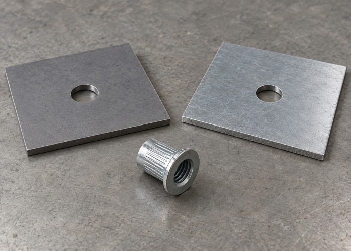
Identify the parent material grade and actual thickness. Include coatings and the stage at which installation occurs. The grip range must suit the actual assembled thickness, while the specified hole geometry must match the selected insert. Sherex’s blind rivet nut data lists grip ranges and hole diameters by individual product, demonstrating why these details belong to the exact part number.
A round hole, a hexagonal hole and a damaged out-of-round opening do not provide the same installation conditions. Record how the hole was produced and any relevant burr or deformation requirements. Do not validate a neatly machined laboratory coupon and silently apply the result to a production hole whose process produces a different edge condition.
Document edge distance, nearby bends and access to the installation tool. A flat isolated coupon may be adequate for one purpose but may omit important features of a formed panel. State which differences are accepted and why. If a panel is supported during testing in a way that the real assembly is not, the result needs that qualification.
Describe the fixture before comparing results
| Variable | What to document | Potential interpretation problem |
|---|---|---|
| Sheet support | Clamping area, opening and contact faces | Fixture changes how the sheet can deform |
| Loading member | Bolt or mandrel identity and engagement | A different component fails before the insert |
| Torque arrangement | How torque is applied and what is restrained | A clamped mating part changes rotation resistance |
| Axial arrangement | Direction and load path | Pull-through and thread failure are confused |
| Endpoint | Defined movement, damage or load criterion | Different stopping rules produce incomparable numbers |
| Sample condition | New, previously loaded or environmentally exposed | Earlier testing changes subsequent behavior |
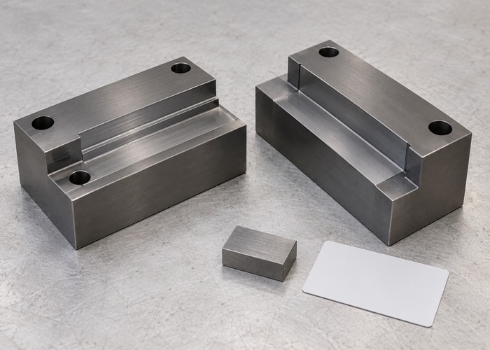
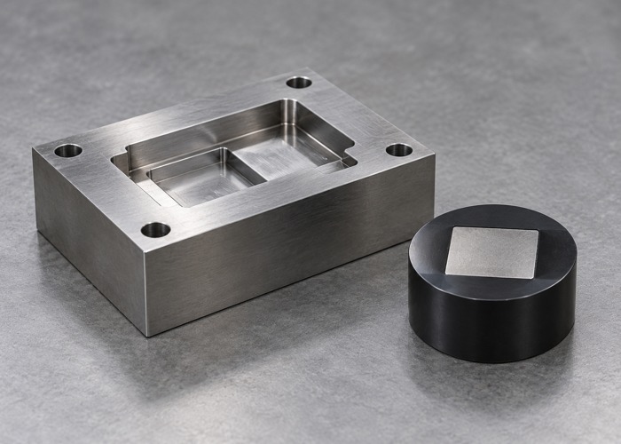
A dimensioned sketch or controlled fixture drawing is more useful than a photograph that hides the clamping arrangement. Record the test procedure and revision, instrument identity and the required equipment verification. For a load-displacement or torque-angle record, retain the underlying data where it is part of the agreed evidence.
A test involving a clamped mating component may behave differently from a test of the insert without that component. Treat the restraint condition as part of the method. The final report should make clear whether it represents a bare insert qualification, a production inspection check or the actual assembled service joint.
Keep installation evidence connected to test specimens
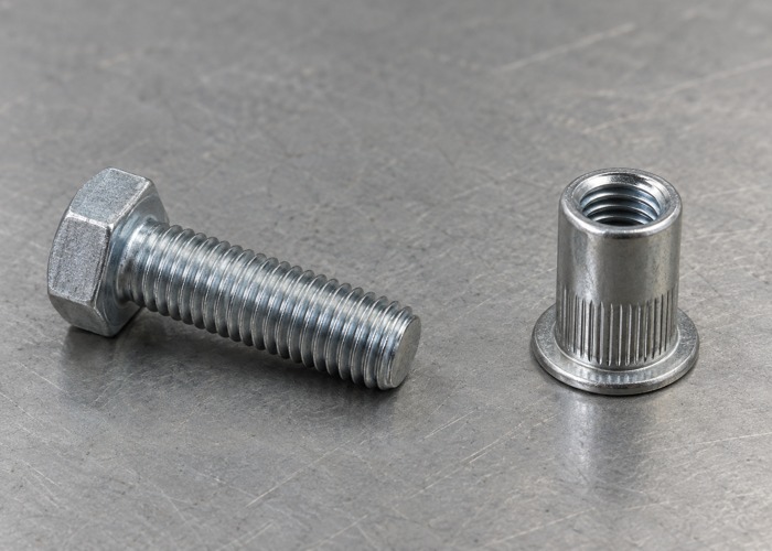
Identify the installation tool, relevant setting or controlled program, insert lot and operator or station record as appropriate. If the process uses monitored force or stroke, retain the required trace. A tool display marked acceptable is useful process evidence, but it does not replace a separately required mechanical test of the installed joint.
Record the installed condition before destructive testing. Note flange seating, visible sheet distortion, damaged threads or other specified characteristics. If the specimen already shows an installation defect, preserve that observation. Removing an inconvenient sample from the test set without explanation prevents the report from representing the actual process.
The inspection plan should connect samples to production events such as setup approval, material change or tool maintenance when those events are relevant. There is no universal sampling frequency for every insert and panel. Agree the plan with the engineering and quality assurance teams before production, including how a failed sample affects the associated lot.
Use an explicit response to failure
When an insert spins or pulls through below the agreed criterion, identify the affected interval and retain the specimen. Compare the actual insert and sheet conditions with the approved specification. A larger installation setting is not an automatic remedy; the investigation should distinguish an incorrect part, unsuitable grip, hole variation, installation deviation and an inadequate joint design.
After an approved correction, document what changed and repeat the required validation. Do not combine results from different configurations into one unexplained average. Keep initial failures and subsequent results visible, with the disposition and reviewer identified. This provides a useful basis for future orders rather than merely producing a passing summary line.
Coordinate changes with any finishing requirements. A change in coating sequence or contact condition may affect both appearance and installation. If the application involves dissimilar materials, also review the broader galvanic-corrosion joint considerations; mechanical test acceptance does not establish corrosion performance.
Questions buyers often ask
Does assembly torque prove spin-out resistance?
It proves only the outcome of that assembly operation under its actual conditions. A formal spin-out requirement needs the agreed specimen, restraint, loading method and endpoint. Do not rename an assembly check as a destructive qualification test.
Can a supplier’s catalog value be the acceptance limit?
Only after the responsible team confirms that the value and its test conditions are suitable for the application. Catalog data is useful for selection, but the actual sheet, hole and joint arrangement must be considered.
What belongs in the quotation package?
Send the fastener part number, sheet specification, hole drawing, grip thickness, finishing sequence and test requirements. Ask FUMING to review the inspection scope so that specimen quantities, destructive testing and report content are included in the manufacturing plan.