A hydraulic core-pull handover needs more than a cylinder part number and two hose connections. The receiving team must know which mechanism moves, its required positions, the hydraulic interface, the meaning of each position signal and the approved sequence with the molding machine. A cylinder that moves successfully on a bench has not established compatibility with the final mold and machine.
For a mold-making project with FUMING, assign responsibility for this interface before tooling release. This guide concerns procurement records and acceptance evidence. Installation, commissioning and abnormal-state recovery must follow the applicable manufacturer instructions and the responsible engineering team’s approved procedures.
Give each moving core a stable identity
Use a mechanism identifier that appears on the mold drawing, hydraulic diagram, electrical record and trial report. Terms such as “left cylinder” become ambiguous when people view the mold from opposite sides. If several cylinders look identical, the identification must still distinguish their functions and connections.
Record the cylinder’s full designation, stroke configuration and any special options. Include the rod connection and mounting arrangement shown in the released design. A replacement selected from appearance alone may differ in travel, mounting, sensing or operating requirements even when it fits in the available space.
Maintain an as-built record of changes made during manufacture or trial. If a bracket, stop, spacer or rod connection is modified, update the appropriate drawing. The receiving team should not have to reverse-engineer an undocumented adjustment to understand the supplied assembly.
Separate useful core travel from cylinder stroke
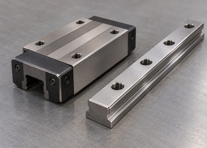
Identify the required core positions in relation to the part and the rest of the mold. The cylinder’s catalog stroke does not explain where the core begins, where it clears the part or how its final position is established. Include the reference surfaces and any approved adjustment range in the drawing package.
Keep the guide system and the driving element distinct. DME’s hydraulic locking core-pull installation instructions state that the cylinder piston is not intended to maintain the sliding core’s positional alignment. For the specified assembly, installation must follow its own guidance rather than assuming the rod can compensate for inadequate guiding.
For another cylinder design, obtain its applicable mounting and load requirements. The handover record should identify which components guide the core, which drive it and which establish or retain its working position. This separation helps procurement avoid treating all cylinders as mechanically interchangeable.
Define the hydraulic interface as a complete connection
Record the port designations and their functions, with a connection map that matches the released hydraulic schematic. Thread identity alone is insufficient: the selected fittings, sealing arrangement, hoses and receiving-machine connections must be compatible with the approved system requirements.
Identify the required hydraulic supply conditions and the responsible party that confirms compatibility. Keep units explicit and distinguish specified requirements from actual trial conditions. This article does not prescribe pressure, flow or temperature values; those depend on the selected equipment, mold design and approved application.
Document hose routing and identification sufficiently for the receiving site to reproduce the intended arrangement. Review exposure to moving components and service access through the engineering process. The handover package should preserve the approved route rather than invite an operator to choose whichever connection is easiest to reach.
Do not confuse a command with position confirmation
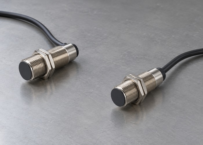
A machine command to move a core is not evidence that the core reached its intended position. The interface record should distinguish the output requesting motion from the input confirming a state. Use the exact signal names in the machine and mold documentation, with clear descriptions of what each state means.
DME’s locking core-pull FAQ emphasizes monitoring the fully forward and retracted positions for its cylinder system. It also discusses different sensor configurations. Use this as a reason to obtain the correct component documentation, not as a universal wiring instruction for every mold.
Record sensor designation, connector identity and the approved wiring reference. Similar-looking connectors do not prove matching pin assignments or compatible signal behavior. Electrical integration belongs to the qualified responsible team; the purchasing record should identify the verified arrangement and its revision.
Review sequence evidence in the actual configuration
Describe the required relationship between core movement, mold opening or closing, ejection and any other interacting equipment. The correct sequence is design-specific. Do not adopt a generic rule that every core must move at the same stage or infer safe clearance from a single successful cycle.
The approved acceptance plan should identify which operating states and fault responses need verification, who performs those checks and what evidence is retained. It should also state which conditions were not tested. A supplier demonstration on a different machine can provide useful evidence without automatically approving the destination installation.
Keep ordinary process confirmation separate from the assessment of safety functions. A position signal shown on a screen is not, by itself, validation of guarding, interlocks or safe recovery. Those responsibilities remain with the parties designated for the complete machine and cell.
A compact handover table
| Item | Required identity or evidence | Review owner |
|---|---|---|
| Mechanism | Core ID, positions and released drawing | Mold design team |
| Drive assembly | Cylinder, mounting and rod connection | Tool supplier and engineering |
| Hydraulic interface | Port map and approved supply requirements | Hydraulic integration team |
| Position feedback | Sensor identity and electrical drawing | Controls integration team |
| Sequence | Approved state relationships and trial results | Commissioning owner |
| Release | Deviations, closure evidence and final revisions | Named acceptance authority |
The owner names above describe roles, not a mandatory organization chart. Assign actual responsibility in the project. If several suppliers share the interface, nominate one person to coordinate unresolved items so that a missing connection detail does not fall between contracts.
Keep the component documentation with the delivered package. DME’s hydraulic locking core-pull product page is an example of a defined product family. The project still needs documentation for the exact supplied version and its approved integration, rather than a generic catalog link alone.
Close deviations before declaring transfer readiness
A trial may reveal a sensor relocation, a connection correction or a change to the mechanical arrangement. Record the original issue, the approved change and the recheck that demonstrates closure. Mark temporary trial arrangements clearly so they are not mistaken for the delivered configuration.
Link this record to the broader injection mold transfer package. Identify destination-site checks that remain open and the conditions for production release. The mold can be ready to ship while still requiring controlled installation acceptance; the report should distinguish those milestones.
Use the quality assurance record to retain final drawings, component identities and verification results. After a replacement or modification, review the affected checks again. A previous passing trial is historical evidence for its configuration, not blanket approval of later changes.
Questions buyers often ask
Does successful cylinder movement prove the core interface is accepted?
No. Movement alone does not establish required position, guidance, signal meaning or sequence compatibility with the installed machine.
Can the same mold use another machine without review?
Compare the receiving machine’s hydraulic and control interfaces with the released records. Coordinate the required verification with the injection molding setup team before production.
What belongs in an RFQ?
Provide the mechanism drawing, receiving-machine information, required component documentation and acceptance responsibilities. Contact FUMING to define the tooling and handover scope before the cylinder arrangement is finalized.