A sprue bushing and machine nozzle interface should be reviewed as a mating system, not selected by a familiar part name. The receiving team needs the nozzle-tip geometry, bushing seat geometry, flow openings, locating arrangement and installed axial relationship. Similar-looking components can still create an unsuitable interface when the mold moves to another machine.
For a mold-making project with FUMING, provide the intended injection machine information before the interface is released. This guide focuses on dimensional records and handover responsibilities. It does not prescribe a universal radius relationship, contact force or nozzle setting for every molding system.
Identify the exact components on both sides
Record the machine nozzle-tip manufacturer, designation and drawing where available. Identify the sprue bushing by complete part number or controlled drawing. Include any custom machining, replacement tip or extension that changes the interface. A machine model alone may not identify the nozzle currently installed on it.
DME’s sprue bushing product overview shows that machine-side seat geometry is part of the component specification. The presence of several configurations is a reason to obtain the actual drawing rather than assume that a standard-looking bushing matches the receiving machine.
Preserve units and drawing revisions. A dimension copied from an old setup sheet may refer to a previous nozzle or a different bushing. Where the receiving site supplies its own nozzle tip, name the person responsible for confirming the installed configuration before trial. This closes a common gap between mold purchasing and machine setup.
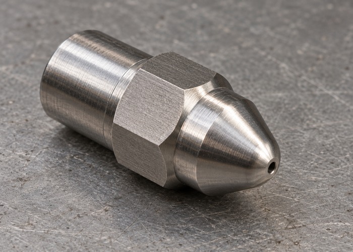
Review the seating geometry without relying on appearance
Identify the nozzle contact surface and the mating bushing seat. Record the specified geometry and applicable manufacturer’s matching requirements. A photograph of two spherical-looking surfaces is not enough to determine compatibility. Keep the dimensioned references available to the engineer reviewing the interface.
Do not apply an informal rule about equal or unequal radii without confirming the requirements for the selected system. Catalog terminology, component design and the intended contact arrangement must be understood together. If a supplier proposes a mismatch intentionally, request the engineering basis and approval rather than treating it as an undocumented shop adjustment.
Review surface condition as well as nominal geometry. Damage, deposits or previous rework can change the actual interface. Record the inspected condition and any approved corrective action. Avoid presenting additional nozzle force as a general solution to an unexplained leak or poor contact; the underlying configuration needs investigation.
Keep the flow openings and alignment in the same review
Document the nozzle exit opening and the sprue inlet geometry. Confirm the intended relationship using the selected component and machine requirements. A suitable contact surface does not automatically establish a suitable flow transition. Likewise, nominally compatible opening sizes do not prove that the openings align in the installed system.
DME’s three-plate extension bushing FAQ specifically calls for attention to the machine nozzle tip, spherical seat and inlet relationship. That guidance belongs to the described assembly. For another design, use its own documentation rather than copying a dimensional rule from an unrelated product.
Identify how the mold is located in the machine and how the nozzle approaches the bushing. Retain the relevant locating-ring, platen and interface references when they are part of the design. A correct loose-part measurement cannot establish the alignment of the complete installed arrangement without the appropriate setup review.
Check the axial relationship and available travel
Record the bushing’s installed position relative to the agreed mold reference surface. Include any extension, recessed arrangement or other feature affecting nozzle reach. The receiving machine must be able to achieve the intended interface under its approved operating requirements. Do not infer this from a catalog stem length alone.
Compare the required position with the machine information supplied by the receiving site. Identify which dimensions are design values and which were verified on the installed mold. If a trial uses a temporary adapter or another nozzle, state that explicitly so the trial does not appear to validate a configuration that was never tested.
Review access for inspection and servicing under the site’s approved procedures. Hot surfaces, pressure and machine movement require the established isolation and handling controls. A purchasing guide should specify the information needed for review, not encourage operators to make live contact checks or improvise adjustments around operating equipment.
Use a compact interface record
| Record item | What to identify | Reason for retaining it |
|---|---|---|
| Nozzle tip | Installed designation and controlled geometry | Machine model does not identify every replacement tip |
| Sprue bushing | Part number, drawing revision and modifications | Links the review to the delivered component |
| Seat relationship | Specified mating geometry and approval basis | Prevents assumptions based on visual similarity |
| Flow transition | Exit and inlet geometry and alignment references | Separates seating compatibility from flow geometry |
| Installed position | Axial reference and receiving-machine requirements | Confirms what the machine must accommodate |
| Trial evidence | Actual configuration, observations and disposition | Defines what was verified at release |
Attach drawings or sketches that make the references unambiguous. A list of dimensions without their origins can be more confusing than a short controlled drawing. State the units and whether a value is nominal, specified with a tolerance or an inspection result. Preserve the acceptance basis alongside the result.
Use photographs to document condition and orientation, while keeping dimensional identity in the controlled record. If photographs show a temporary setup, label that condition in the handover package. The next team should not need to infer which image represents the final released mold.
Distinguish installation status from supplied components
A component included with a mold base is not necessarily installed and verified. DME’s sprue bushing FAQ distinguishes supply and installation arrangements. In a project purchase order, state who machines the installation features, fits the component and verifies the final position.
Record any machining performed after the catalog component is received. If the finished bushing differs from the standard drawing, retain an as-built reference and identify what a replacement must reproduce. Ordering the same catalog number later may not recreate an undocumented modification.
Include this responsibility in the quality assurance handover. A complete bill of materials helps procurement, but the release package also needs evidence that the installed interface matches the approved configuration.
Reconfirm the interface when transferring the mold
At transfer, obtain the receiving machine’s actual nozzle information and compare it with the released interface record. Do not assume that a previous successful trial establishes compatibility with every machine in the same size class. Identify differences before the mold arrives for production.
The mold transfer checklist provides broader receiving-site context. Keep the nozzle interface as a specific item within that package, with an owner and a documented disposition. If a different tip is required, include its supply and verification responsibilities in the transfer plan.
During the agreed trial, record the actual configuration and relevant observations. A change made during troubleshooting should be reflected in the final documents. Coordinate the accepted arrangement with the injection molding setup requirements, keeping interface evidence separate from the broader process qualification.
Questions buyers often ask
Does the same nominal seat radius prove compatibility?
No. Review the selected system’s complete mating requirements, flow openings, alignment and installed position. Use controlled component information rather than one isolated dimension.
Can the old machine setup sheet be reused after transfer?
It is useful history, but the receiving machine and installed nozzle must be checked against the mold interface. Record any differences and required approval.
What information should accompany an RFQ?
Send the nozzle-tip drawing, machine interface information, intended bushing arrangement and required trial evidence. Contact FUMING to define installation, verification and handover responsibilities before tooling release.