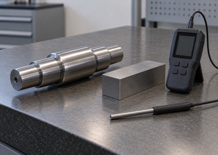
A useful shaft runout report identifies the drawing requirement, the datum features used to establish rotation, the inspected surface and the measurement coverage. A small indicator reading is not sufficient evidence if the part was supported from a different reference. Before comparing supplier results, confirm that both reports describe the same geometric requirement and the same datum relationship.
This guide addresses inspection planning for CNC machined parts. It focuses on the acceptance record rather than prescribing one universal fixture. Send FUMING the controlled drawing and the intended mating conditions so that the manufacturing and inspection teams can review the requirement together.
Identify the actual control before choosing a fixture
Circular runout and total runout are different controls. In its geometric tolerance guide, Mitutoyo distinguishes a circular element relative to the datum from a surface controlled relative to that datum. The drawing standard and complete feature control frame govern interpretation. A shop description such as “check wobble” leaves too much unspecified for a release decision.
Record the controlled feature, specified direction and datum references. Identify whether the requirement concerns a cylindrical journal, a face or another permitted surface. Do not convert an axial face check into a radial journal result simply because both are obtained during rotation. They answer different questions about the component.
Also separate runout from size and form checks. A diameter result does not establish runout, and a roundness result does not by itself establish the relationship to the required datum axis. The existing roundness inspection guide covers the distinction between size and circular form; this record adds the specified reference relationship.
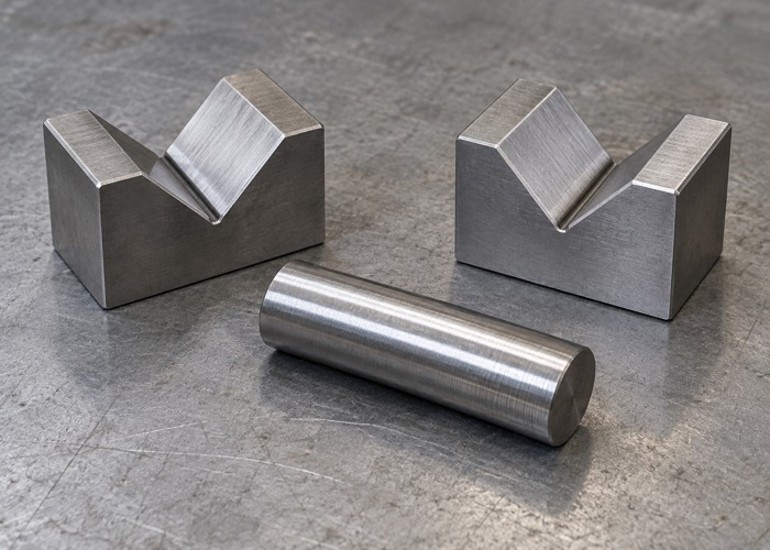
Make the datum realization visible
Describe which physical features contact the fixture and how they are located. If the drawing references a journal, identify that journal in the setup record. Centers, a chuck, a collet or support blocks may be useful in a particular procedure, but their presence does not automatically demonstrate that the drawing datum has been established correctly.
A fixture photograph should show contact locations, axial restraint and the inspected region. Pair it with a sketch when the important contacts are hidden. Record any procedure or fixture revision that defines how the part is seated. The person reviewing the result should not have to infer the setup from a cropped image of the indicator dial.
Consider whether support, clamping or restraint changes the part’s condition. A slender shaft can behave differently under different supports. The responsible metrology team should validate the chosen method for the requirement rather than treating the machining setup as an inspection specification. Record any agreed restrained condition explicitly.
Distinguish alignment adjustments from removing the error
Centering and leveling are legitimate parts of many measurement procedures, but the reference used for those adjustments matters. If the controlled surface is independently aligned until its variation becomes small, the procedure may remove the very relationship that the drawing requires. Preserve the datum construction and evaluation settings in the inspection record.
This is especially important when comparing a rotary instrument with a coordinate measuring machine. Ask how the datum was established, which points or traces were acquired, and what evaluation was applied. The instrument name alone does not establish equivalence. The Mitutoyo roundness instrument catalog illustrates different form and runout measurement tasks; choosing a capable system is only the beginning of defining a suitable procedure.
Keep alignment parameters available for review when they influence the reported result. If a program revision changes point selection or datum construction, identify that revision on the report. A result that changes after a software setting change needs an explanation, not merely a new passing number.
Define the coverage behind the reported value
| Record item | Question it answers | Common omission |
|---|---|---|
| Controlled region | Which surface was evaluated? | Only an accessible end was checked |
| Datum realization | What established the reference? | Fixture contacts are undocumented |
| Axial positions or scan path | Where was data collected? | A single section represents a longer surface |
| Angular coverage | Was the required rotation evaluated? | A limited accessible arc is treated as complete |
| Excluded regions | Which interruptions were omitted? | Keyways or damaged areas vanish from the report |
| Evaluation method | How was the result calculated? | Software defaults replace an agreed procedure |
A total-surface requirement cannot be established simply by labeling one local reading “total runout.” Plan coverage appropriate to the surface and the applicable requirement. Sampling limitations should remain visible, particularly where access, grooves or interrupted features prevent straightforward acquisition. Agree the treatment of interruptions before testing production parts.
Retain the underlying trace or measurement data where it is required for acceptance. A single summary value may be suitable for routine release once the method is established, but qualification or a disputed result may require more evidence. State what data will accompany the report and what will remain available on request.
Check repeatability before interpreting a disagreement
If two setups disagree, start by confirming part identity, drawing revision and measured region. Inspect the relevant contacts for contamination or damage using the approved handling procedure. Then compare seating, axial restraint and reference construction. Repeating a measurement without documenting what changed can produce a collection of values without resolving the cause.
A controlled remove-and-reseat exercise can help investigate setup sensitivity when the responsible team specifies how it is performed. Keep individual results instead of retaining only the most favorable reading. Record the operator, instrument and fixture identities so that the investigation can distinguish method variation from a real change in the component.
Near a tolerance boundary, follow the agreed decision rule and uncertainty treatment. The measurement uncertainty acceptance guide explains why an instrument’s display resolution is not the same as confidence in a release decision. Do not resolve conflicting results by averaging measurements that used incompatible setups.
Connect the report to manufacturing changes
Identify the stage of manufacture represented by the inspection. Results before a later thermal, finishing or assembly operation may not describe the delivered condition. If an intermediate check is useful for process control, label it accordingly and preserve the final acceptance requirement. This prevents a valid in-process record from being used for an unintended purpose.
When a corrective action changes workholding or the sequence of operations, review whether the inspection method remains suitable. Keep process adjustments separate from drawing changes. A supplier may improve the method used to achieve the requirement, but changing the requirement itself needs the appropriate engineering authorization.
The quality assurance plan should name the required report, sampling scope and escalation path. Mitutoyo’s precision measurement guide offers further background on form measurement; the released drawing and approved procedure remain the references for the individual part.
Preserve the units and the original unrounded result where the agreed reporting procedure requires it. If a report displays rounded values, explain the rounding convention. A formatting change should not silently change the basis on which a borderline part is accepted or rejected.
Questions buyers often ask
Can a passing diameter check replace runout inspection?
No. Size and the specified relationship to a datum are separate requirements. Ask for the inspection evidence corresponding to each drawing control.
Must every shaft be measured between centers?
No universal setup applies to every shaft. The fixture and evaluation must establish the specified datum relationship and suit the part’s geometry and condition.
What should accompany a quotation request?
Provide the drawing revision, datum features, controlled surfaces and required inspection evidence. Contact FUMING to agree the reporting scope before production, including any customer fixture or correlation study that must be included.