An optical measurement program for machined parts should be qualified against the actual feature, surface condition and loading method used in production. A sharp image and a repeatable number are useful, but neither proves that the system has identified the intended physical boundary. Buyers need evidence linking the drawing requirement to the edge selected by the inspection program.
For a CNC machining project with FUMING, define the features that will use optical inspection and the evidence required for approval. This guide concerns program validation and transfer. It does not prescribe a camera, advertise an equipment capability or replace the dimensional acceptance requirements on the drawing.
Start with the boundary that matters
A hole can present several visible boundaries: its entrance, a chamfer transition and an opening on the opposite face. Before programming, identify which boundary represents the specified dimension. An automatically detected circle may be consistent while referring to a different feature from the one the buyer intended.
Use the drawing and a controlled feature map to connect each reported result to its location. Record the relevant face and viewing direction. If the drawing requirement concerns a depth, internal form or inaccessible surface, establish whether the chosen optical method can actually evaluate it.
KEYENCE’s optical CMM overview describes image-based measurement and notes that some systems add other sensing methods. Treat that as a reminder to match the measurement method to the feature, not as proof that every visible feature can be accepted using one camera view.
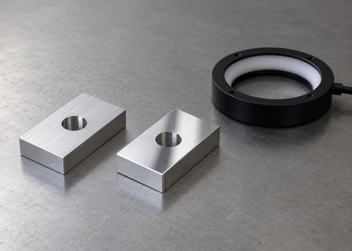
Preserve the lighting conditions in the program record
Lighting is part of the measurement setup. Record the illumination type and the settings that affect the selected feature, together with the equipment and program identity. A screenshot alone may not preserve enough information to recreate the condition after the program is transferred or edited.
The KEYENCE lighting selection guide distinguishes backlighting for silhouettes from lighting arrangements used to reveal reflective surfaces. This distinction matters when deciding whether the inspection is locating an outer profile or a feature on the upper face.
Mitutoyo’s vision-system information also describes illumination choices that emphasize edge contrast. These equipment examples support controlling the lighting condition; they do not establish a universal setting for aluminum, steel or any particular finish.
Challenge the setup with representative surfaces
A program developed on one unusually clean sample may not represent the surfaces encountered in the approved process. Select samples that cover the relevant range of finish and appearance. Document why those samples represent production instead of simply choosing the easiest parts to measure.
Include the permitted part condition in the inspection instruction. Distinguish a clean final surface from a surface carrying temporary oil, protective film or processing residue. Do not quietly remove a required finish or alter an edge to make the image easier to analyze.
If a surface change affects the result, preserve the original observations and investigate the cause. The question is whether the measurement still represents the specified boundary. Adjusting contrast until the result agrees with an expected number is not a substitute for establishing that connection.
Separate repeatability from agreement with a reference
Repeated captures without moving the part test only a limited portion of the process. A more useful validation plan can also include removal and reloading, different permitted orientations and the operators who will use the instruction. Agree the plan and acceptance criteria before collecting the approval data.
Where another method is used for comparison, confirm that it measures the same feature definition. A contact measurement at one height and an optical silhouette at another location may not be directly comparable. Investigate those differences before treating either result as the correct answer.
Keep this work connected to the project’s measurement uncertainty and acceptance agreement. Program repeatability is one piece of evidence. It does not by itself establish the complete uncertainty or the decision rule for a result near a specification limit.
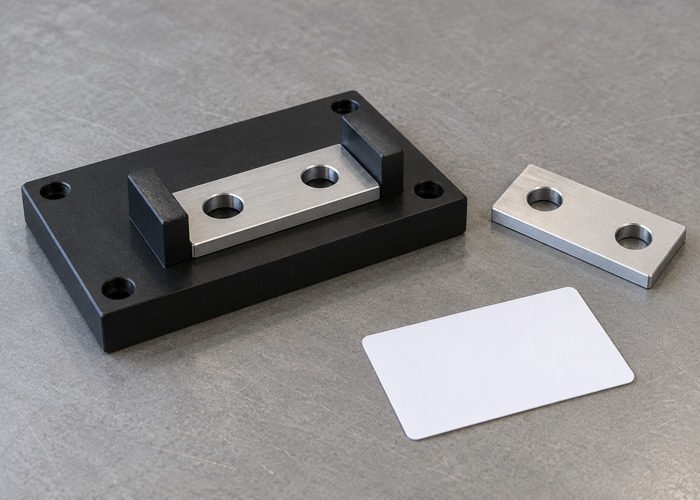
Control loading, alignment and focus
Describe the locating surfaces and supports used to present the part. A fixture photograph should show how the relevant face is oriented and how the part is seated. Avoid an instruction that depends on an operator remembering an undocumented preferred position.
Record the alignment strategy and the features used to establish the coordinate system. If the program uses automatic alignment, retain enough information to identify the features it recognizes. A successful alignment message is not evidence that it selected the intended datum features on every sample.
Focus and image-processing settings should follow the approved measurement method. Where automatic functions are used, challenge them across the agreed sample range. A manual intervention should be recorded rather than hidden within a report that appears to describe an unchanged automatic process.
Make the approval package reproducible
| Record | What to retain | Review question |
|---|---|---|
| Feature identity | Drawing reference, face and selected boundary | Is the intended geometry measured? |
| Program | Controlled identifier and revision | Can the approved setup be recovered? |
| Presentation | Fixture, orientation and loading instruction | Can another operator reproduce it? |
| Optics | Lighting, focus and relevant processing settings | Are image conditions controlled? |
| Validation | Sample identities, comparisons and repeated loads | What range was actually tested? |
| Disposition | Criteria, limitations and approval | What work is released? |
Retain the original comparison results, including disagreements and excluded observations with their reasons. An approval summary should point to that evidence. A table containing only the final selected numbers can conceal the conditions that caused the program to behave differently.
Keep representative images associated with the corresponding sample and result. Images help a reviewer understand edge selection, but they should not replace the numerical record or the controlled program. Store them with enough context to distinguish an approved setup from a development trial.
Define when the program needs another review
Changes to the part revision, finish, fixture, optics or measurement software may affect the original validation scope. Establish a change-review process that asks whether the altered condition was covered. Do not automatically assume that a familiar program name means the measurement remains equivalent.
For a transferred program, identify the receiving equipment and verify the conditions that matter to the feature. The same file can run on a different setup without reproducing the same result. Record the transfer evidence and any approved limitations before using it for shipment release.
If the review identifies a problem, define the affected inspection period and parts using the inspection equipment failure review where relevant. Preserve the previous program revision and results while the technical team assesses the impact. Keep corrections traceable rather than overwriting history with a revised report that hides the original condition.
Buyer questions before release
Is a clear image sufficient evidence of measurement accuracy?
No. It helps identify visible features, but the method must still represent the specified geometry and satisfy the agreed validation requirements. Ask for the feature mapping and comparison evidence, not only a screenshot.
Can optical inspection replace every contact measurement?
That decision depends on the feature and validated method. Some requirements concern geometry that is not established by the selected view. Keep the inspection plan specific rather than assuming one technology covers the complete drawing.
What should be sent with a production approval request?
Provide the controlled program identity, representative sample results, loading instruction and unresolved limitations as part of the quality assurance record. Contact FUMING to align the inspection evidence with the part requirements before release.